Valve Setup
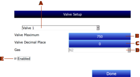
The MGA 6010 uses four flow control valves for nitriding gas analysis. These valves are enabled and set up in the Valve Setup window.

The Valve Setup window contains the following items:
A – Valve Selection Drop-Down List. Using this drop-down list, you can select the valve number ( through 4) that you want to configure.
B – Valve Maximum. This field is used to set the maximum valve that can be entered for the valve gas flow. Tap on the field to change it.
C – Valve Decimal Place. This field is used to set the number of decimal places that will be used in the valve gas flow value in the Nitrider Calculation page. For example, if the valve decimal place is set to “1” in this menu, and “600” is entered for valve 1 flow on the Nitrider Calculation page, the displayed value will be “60.0”. NOTE: This field will also change the number of decimal places used for the Valve Maximum field in the Valve Setup menu.
D – Gas Selection Drop-Down List. This drop-down list allows you to select the gas used in the selected flow control valve. If used, valve 1 must be used with N2, and valve 2 must be used with NH3 (these are fixed). Valve 3 may be used with Dissociated Ammonia (DA), NH3, a miscellaneous gas (Misc), endothermic gas (Endo), or CO2. Valve 4 may be used with H2, NH3, a miscellaneous gas (Misc), endothermic gas (Endo), or CO2.
E – “Enabled” checkbox. If this box is checked, the selected flow control valve number is enabled and will be displayed on the Nitrider Calculation page. If it is not checked, the valve is disabled; it will not be displayed on the Nitrider Calculation page.
When finished with valve setup, tap the “Done” button.